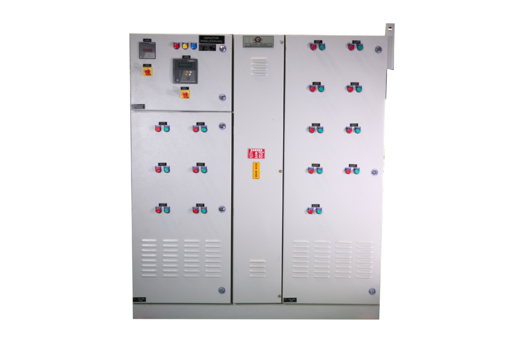
APFC Panel are essential in industrial settings where inductive loads, such as motors, can lead to a low power factor (typically below 0.95). By correcting the power factor, these panels help reduce energy costs and improve the overall efficiency of the electrical system.
Key Features
Power Factor Correction
Correction Range: Capable of improving power factor up to 0.95 to 0.99
Automatic Switching: The panel automatically engages or disengages capacitor banks based on real-time reactive power requirements.
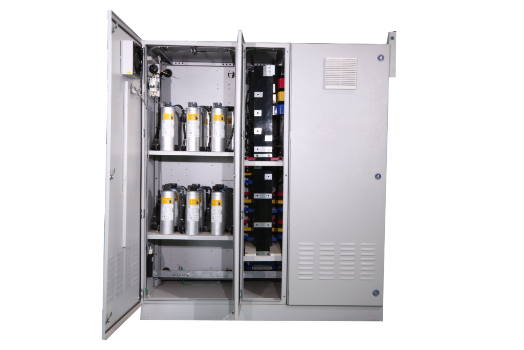
Detuned Reactor Facility
Harmonic Mitigation: Incorporates detuned reactors (available in aluminium and copper winding) to prevent harmonic amplification and resonance, which can adversely affect system performance.
Capacitor Bank Configuration
Flexible Design: Capacitor banks are configured in smaller steps to match the reactive power needs of the load accurately.
Switching Options: Users can choose between capacitor duty contactors or thyristor-based switching for smoother operation and reduced electrical stress.
Applications
APFC Panels are widely used in various industries including:
Manufacturing Plants
HVAC Systems
Water Supply and Irrigation
Fertilizer Production
Steel Industries
These applications benefit significantly from improved power factors, leading to reduce energy costs and enhanced equipment longevity.
Advantages
Energy Efficiency: By maintaining an optimal power factor, these panels help minimize energy wastage and reduce electricity bills.
Equipment Protection: Reduces stress on electrical equipment by mitigating harmonics and improving voltage stability.
Cost Savings: Lower operational costs due to reduced penalties from utility companies for low power factors.
RATED VOLTAGE
415V AC TO 690V AC
SHORT TIME RATING
UP TO 70 KA FOR 1 SEC
PHASE/FREQUENCY
3PHASE/50Hz
TYPE TESTED
SHORT CIRCUIT CURRENT/TEMP RISE/ DEGREE OF PROTECTION
REFERENCE STANDARD
IEC:60439-1, 2009, IS:8623
FORM OF SEPERATION
3B/ 4B
BUS BAR
ALUMINUM AND COPPER
SIZE OF BAY
2400 MM(H); 1200 MM(W); 1600 MM (D)
AMBIENT TEMPERATURE
45 DEGREE CELSIUS
FEEDER CONFIGURATION
FIXED TYPE FOR AUTOMATIC POWER CORRECTION
APPLICATION
MCC-PROTECTION & CONTROL OF MOTORS; PCC-POWER DISTRIBUTION & CONTROL OF MAIN & D.G SUPPLY